-
Products

- guatemala
Displaying items by tag: guatemala
V RESIDENTS CONGRESS OF CRITICAL MEDICINE AND ADULT INTENSIVE CARE.

"Improving healthcare with advanced technology"
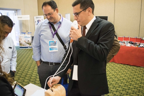
We are a company dedicated to the distribution, installation and technical service of medical equipment and on this occasion we were present at the V RESIDENTS CONGRESS OF CRITICAL MEDICINE AND INTENSIVE ADULT CARE that took place at Casa Ariana..

Presenting one of our newest products Ambu® AVIEW High Resolution Portable Monitor , we thank those who made the activity that was carried out a success, demonstrating the ease and quality of intubation
Understanding the anesthesia machine
Understanding the anatomy of anesthesia machines is essential for their safe use. It is more difficult to understand them today given the advanced technology with which they are built; until a few years ago, knowledge of simple pneumatic systems was sufficient.
Currently, electronics and even computing are additionally required. You must know the differences between the different models to perform the necessary pre-use checks.
An anesthesia system consists of several components that communicate with each other during the administration of inhaled anesthesia. Components include the anesthesia machine, vaporizers, and respiratory system. This guide covers the functioning, operation and integration of the main components of the system. Likewise, it includes the security measures and limitations of each one. Finally, procedures proposed to verify pressures of the circuit and the respiratory system are described.
HIGH PRESSURE CIRCUIT
Oxygen cylinders, nitrous oxide cylinders, coded yokes for both gases, anvil gaskets, pressure gauges installed on the anvils and the upper chamber of the reducing valve are considered elements of the high pressure circuit.
Leaks in this circuit are very common due to the high pressures that are handled; for oxygen up to 2000 psi and for nitrous oxide up to 1000 psi.
Steps to follow to determine leaks:
- Close flowmeters
- Open oxygen and nitrous oxide cylinders
- Close the cylinders
- Check through the pressure gauges of both cylinders that there is no pressure loss
If the pressure drops very quickly, the leak should be heard, if not, it is recommended to wet all the connections with a solution based on water and soap, this will allow you to visually determine the exact location of the leak, if The leak is detected in the reducing valve, it will surely be necessary to change the diaphragm and recalibrate it.
MEDIUM OR REGULATED PRESSURE CIRCUIT
This part of the anesthesia system works with a pressure called “working”, its value ranges between 45 and 60 psi. Internal circuits, in-line pressure gauges, one-way checks, hoses, coded taps, fail-safe and flush are constantly subject to this pressure.
In the same way as the high pressure circuit, the easiest way to determine leaks is through the pressure gauges on this line.
The most difficult leak to determine is usually found in the flush or emergency valve. The passage valve inside the flush is identical to the centers of car tires. Replacing it resolves the leak in most cases.
THE ANESTHESIA MACHINE
Figure No. 1 shows a generic anesthesia machine, equipped with circuits for two gases, oxygen (O2) and nitrous oxide (N2O). Both circuits are supplied from two sources, wall system and cylinder system. The wall system is considered as the primary source for the anesthesia machine. These systems provide gases to the machine with an approximate pressure of 50 pounds per square inch (psi), which is the normal working pressure for this type of equipment. The cylinders are considered an emergency source in the event that the primary source fails, the pressure of the oxygen cylinders is regulated from 2000 psi to 50 psi and from 1000 psi to 50 psi for the nitrous oxide cylinders.
A safety system usually known as fail-safe is located near sources of nitrous oxide. This device shuts off the flow of nitrous oxide (and other gases) when oxygen pressure drops. Typically the fail-safe is activated when the oxygen pressure drops below 30 psi. Additionally, some machines have an audible alarm (ritchie whistle) that activates when pressure drops.
The control valves of the flowmeters are of special importance in the anatomy of the anesthesia machine; they separate the medium pressure circuit from the low pressure circuit. The operator regulates the flow entering the low pressure circuit by adjusting these valves. The total flow moves through a central manifold, located at the top of the flowmeters, which is communicated to the vaporizers. Specific amounts of halogenated anesthetic can be added to the gases depending on the position of the dial on the vaporizer. The final mixture flows through the common gas outlet.
FLOWMETERS EQUIPPED WITH DEVICES TO AVOID HYPOXIC MIXTURES (PROPORTIONAL SYSTEMS)
Recently manufactured machines have proportional systems with the purpose of avoiding administration of hypoxic mixtures. Nitrous oxide and oxygen are linked by a device in such a way that the minimum oxygen concentration in the common gas outlet is 25%.
In mechanical systems, the control valves of the flowmeters are connected by a chain similar to that of a bicycle. When you turn the nitrous oxide valve, you automatically turn the oxygen valve, thus maintaining the mixture proportion.
The pneumatically operated devices are composed of an oxygen chamber, a nitrous oxide chamber and the nitrous oxide slave valve, all connected by a small shaft with horizontal movement. Additionally, at the base of both flowmeters there are resistors that produce negative pressure towards the oxygen and nitrous oxide chambers. The negative pressure vapor these resistors receive will dictate the controlled oxygen concentration. This pressure in turn activates the shaft that allows or does not allow the passage of nitrous oxide.
LIMITATIONS ON PROPORTIONAL SYSTEMS
The systems described above are not a guarantee. Machines equipped with these devices under the following conditions may provide a hypoxic mixture.
- Wrong gas source
- Malfunction in the pneumatic or mechanical system
- Administration of an inert gas
- Circuit leaks
It is important to remember that both systems, the pneumatic and the mechanical, work based on the provided pressures. It is not possible for them to recognize the composition of the gas itself.
VAPORIZERS
The vaporizers are located to the right side of the flowmeters. The general principle of operation of a vaporizer can be seen in Figure # 2. The total flow of gases enters the vaporizer and is divided into two parts; The first: which represents a little less than 20% passes through the vaporization chamber, suturing itself from the anesthetic agent, and the second passes directly to the outlet of the vaporizer. Finally, both flows mix when leaving the vaporizer. The proportion of the partial flows will depend on the resistance of the different paths that the gases follow. The concentration dial will vary this resistance depending on its position.
Vaporizers are extremely delicate units, whose constant maintenance is vital for the proper functioning of the anesthesia machine. The only way to determine if the vaporizer is working properly is through an anesthetic gas analyzer. This device allows you to determine if the anesthetic concentration obtained in the common gas outlet coincides with what is indicated on the vaporizer dial. When the readings are far from what is indicated on the dial, it will be necessary to send the unit for inspection by the manufacturer or technicians familiar with this type of device.
CLASSIFICATION OF DIRECT READING VAPORIZERS
Direct reading vaporizers can be grouped in various ways. The most commons are:
- Because of the anesthetic
- Halothane
- Enflurane (etrane)
- Isoflurane (forane)
- Sevoflurano (sevorane)
- Desflurane
- For the color
- Rojo (Halothane)
- Orange (Etrane)
- Magenta(Forane)
- Yellow (Sevorane)
- Celeste (Desflurane)
- For the filling
- Encoded
- Not encoded
- By the Model
- Tec II
- Tec 3
- Tec IV
- TecV
- Tev VI
- For the assembly
- bar
- Selectatec
In our environment, non-thermocompensated vaporizers (vernitrol) are still common. These units are directly connected to the medium pressure circuit. Vernitrols are susceptible to temperature changes, requiring a special graph to interpret the output concentrations.
THE ABSORPTION CIRCLE
The absorption circle is the most popular respiratory system that exists. (Figure No. 3). It consists of eight basic components:
Fresh gas inlet
- Inspiratory and expiratory valves
- corrugated pipes
- “Y” piece
- Relief valve and gas bypass
- respiratory bag
- Canister for soda lime.
- Pressure gauge
Inspiratory and expiratory valves are incorporated into the system to ensure unidirectional flow in the corrugated tubes. The fresh gases enter the circle through a connection to the common outlet of the machine.
The advantages of the circular system include relative constancy of inspired concentration, conservation of humidity and temperature in the respiratory system, and reduction in operating room contamination. In addition, it can be used for the administration of anesthesia with a closed system and for the use of low flows.
Its biggest disadvantage is the complexity of its design. This system has several connections that are potential places for leaks to occur. Faultily operating valves can cause serious problems. Rebreathing can occur if the valves become stuck on the top of the dome. A complete occlusion is possible if it remains stuck at its base.
PRE-USE CHECK
For all the parts and circuits described above there are pre-use check routines. They will be developed using the equipment installed in your hospital.