
Additional Info
- Url marca https://famed.com.pl/es/
Published in
Marcas

Additional Info
- Url marca https://www.equimed.com.gt/es/
Published in
Marcas

Additional Info
- Url marca https://www.equimed.com.gt/es/
Published in
Marcas

Additional Info
- Url marca https://www.equimed.com.gt/es/
Published in
Marcas
|
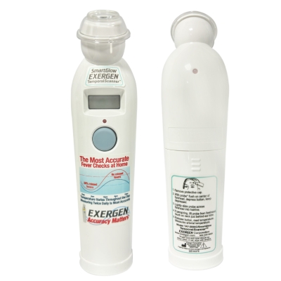
Can be used with: newborns, babies, children or adults. |
| No invasive |
|
Time displeyd on screen: 30 seconds |
| Size: 17,8 cm x 4,45 cm x 3,18 cm |
|
Battery: 1 9v alkaline |
Additional Info
-
imagen de marca

Published in
Products
Tagged under
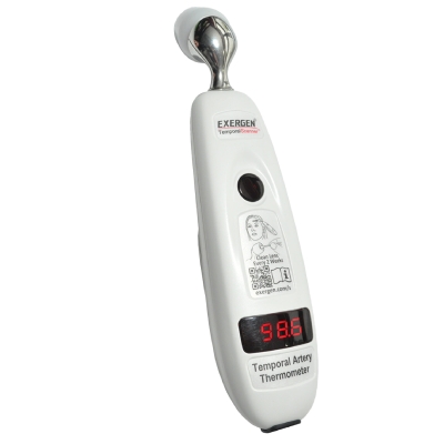
| Can be used: newborns, babies, children or adults. |
|
Very precise temperature measurement. |
| No invasive |
|
Manufactured for indutrial and intitutional use |
| Size: 5 cm x 20 cm x 3 cm. |
Additional Info
-
imagen de marca
Published in
Products
Tagged under

Additional Info
- Url marca https://www.raumedic.com/
Published in
Marcas

Published in
Marcas

Additional Info
- Url marca https://www.myairlife.com/es/del/
Published in
Marcas
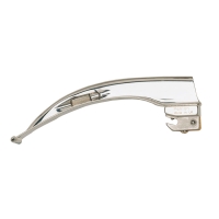
| SIZE | |
| PE-151 | MAC MR LARYNGOSCOPE BLADE NO.2 |
| PE-152 | MAC MR LARYNGOSCOPE BLADE NO. 3 |
| PE-153 | MAC MR LARYNGOSCOPE BLADE NO. 4 |
Additional Info
-
imagen de marca

More...
El CPR assist de Nihon Kohden ayuda a realizar y mantener una RCP de alta calidad
| La forma de onda de la RCP y el valor de medición se pueden ver en tiempo real junto a otros parámetros, como ECG, SpO2 , CO2 y NIBP en la pantalla del desfibrilador. |
| La información necesaria para el rescate cardíaco se puede contrastar en una sola pantalla. |
| Minimiza las interrupciones en las compresiones. |
| El CPR assist indica la velocidad y la profundidad de las compresiones mediante indicaciones luminosas y acústicas. |
Additional Info
-
imagen de marca

Published in
Products
Tagged under
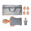
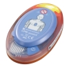
It is an effective training manikin, ideal for CPR training, which is also suitable for training the correct placement of AED electrodes.
Additional Info
-
imagen de marca

Published in
Products
Tagged under
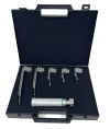
| Palas |
| No. 1 |
| No. 2 |
| No. 3 |
| No. 4 |
| No. 5 |
Additional Info
-
imagen de marca
Published in
Products
Tagged under
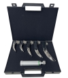
| Blades |
| No. 00 |
| No. 0 |
| No. 1 |
| No. 2 |
| No. 3 |
Additional Info
-
imagen de marca
Published in
Products
Tagged under
